Line Following Robot
Required Components :-
1. Zero PCB Board
2. IR Infrared Obstacle Avoidance Sensor Module
3. 16 pin Ic base
4. L293d ic base
5. 60W Multi Purpose Hot Melt Glue Gun
6. 7805 voltage regulator
7. wood bit (10cm x 5cm x 2.5cm)
8. BO Motor L Type - 60 RPM
9. Red BO Motor Wheels
10. plexiglass piece (10 x 5 cm)
11. soldering wire 50gm
12. Yellow Soldering Iron
13. 10K ohm Variable Resistor
14. Resistor(100ohm, 1k, 10K) etc.
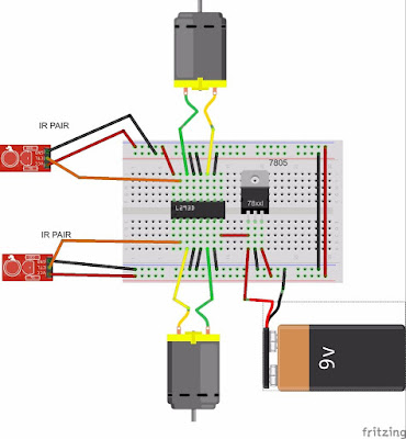
Diagram:
Line Follower Robot using Arduino
source code:
/*------ Arduino Line Follower Code----- */
/*-------definning Inputs------*/
#define LS 2 // left sensor
#define RS 3 // right sensor
/*-------definning Inputs------*/
#define LS 2 // left sensor
#define RS 3 // right sensor
/*-------definning Outputs------*/
#define LM1 4 // left motor
#define LM2 5 // left motor
#define RM1 6 // right motor
#define RM2 7 // right motor
#define LM1 4 // left motor
#define LM2 5 // left motor
#define RM1 6 // right motor
#define RM2 7 // right motor
void setup()
{
pinMode(LS, INPUT);
pinMode(RS, INPUT);
pinMode(LM1, OUTPUT);
pinMode(LM2, OUTPUT);
pinMode(RM1, OUTPUT);
pinMode(RM2, OUTPUT);
}
{
pinMode(LS, INPUT);
pinMode(RS, INPUT);
pinMode(LM1, OUTPUT);
pinMode(LM2, OUTPUT);
pinMode(RM1, OUTPUT);
pinMode(RM2, OUTPUT);
}
void loop()
{
if(digitalRead(LS) && digitalRead(RS)) // Move Forward
{
digitalWrite(LM1, HIGH);
digitalWrite(LM2, LOW);
digitalWrite(RM1, HIGH);
digitalWrite(RM2, LOW);
}
if(!(digitalRead(LS)) && digitalRead(RS)) // Turn right
{
digitalWrite(LM1, LOW);
digitalWrite(LM2, LOW);
digitalWrite(RM1, HIGH);
digitalWrite(RM2, LOW);
}
if(digitalRead(LS) && !(digitalRead(RS))) // turn left
{
digitalWrite(LM1, HIGH);
digitalWrite(LM2, LOW);
digitalWrite(RM1, LOW);
digitalWrite(RM2, LOW);
}
if(!(digitalRead(LS)) && !(digitalRead(RS))) // stop
{
digitalWrite(LM1, LOW);
digitalWrite(LM2, LOW);
digitalWrite(RM1, LOW);
digitalWrite(RM2, LOW);
}
}
{
if(digitalRead(LS) && digitalRead(RS)) // Move Forward
{
digitalWrite(LM1, HIGH);
digitalWrite(LM2, LOW);
digitalWrite(RM1, HIGH);
digitalWrite(RM2, LOW);
}
if(!(digitalRead(LS)) && digitalRead(RS)) // Turn right
{
digitalWrite(LM1, LOW);
digitalWrite(LM2, LOW);
digitalWrite(RM1, HIGH);
digitalWrite(RM2, LOW);
}
if(digitalRead(LS) && !(digitalRead(RS))) // turn left
{
digitalWrite(LM1, HIGH);
digitalWrite(LM2, LOW);
digitalWrite(RM1, LOW);
digitalWrite(RM2, LOW);
}
if(!(digitalRead(LS)) && !(digitalRead(RS))) // stop
{
digitalWrite(LM1, LOW);
digitalWrite(LM2, LOW);
digitalWrite(RM1, LOW);
digitalWrite(RM2, LOW);
}
}
............................................................................................................................................................
.


No comments:
Post a Comment